HOME MG TF 115
Cheater Covers
MG TF
'THE CAR'
CENTRAL LOCKING REAR SPEAKERS
DOOR MIRRORS CHEATER COVERS REAR GRILL
ICE & SATNAV HANDS FREE PHONE BOOT RELEASE

To return to Garvin's Motoring World Portal click on either of the MG logos above

General

This is one design for covers to fit over the open, and rather ugly, slots in the cheater panels which are left exposed when powered mirrors have been installed to replace the manually operated mirrors.

Tools required for the job are:-

  • Work bench and vice.

  • Fretsaw or junior hacksaw with fine toothed blade.

  • Fine grade flat file and/or fine grade sandpaper and block.

  • Strong glue suitable for bonding both plastic and metal.

  • Drill plus 2mm diameter drill bit.

  • Ruler and pencil.

  • Hammer.

  • Panel pin or similar.

  • Methylated spirit or similar solvent and clean applicator cloth or cotton bud.

Parts required for the job are:-

  • 4mm thick black ABS plastic sheet

  • 2mm diameter steel rod (2 x 6mm lengths)

  • 16mm x 16mm MG lapel pin badge x 2 (Optional)


The Finished Articles

Shown right is a photograph of the two made up covers prior to installation. These have a black/white MG lapel pin badge bonded onto the face plate but these are optional and the covers can be left plain black if required.

The design uses the octagonal theme of MG badge with bevelled edges for neatness.

The cover is fabricated from 4mm thick black ABS plastic sheet and comprises a face plate to which an inverted 'T' section back plate is fixed. The back plate then simply pushes through the slot in the flexible rubber cheater panel and the top of the 'T' locates the cover in place.


Design Schematic

Below is shown the design schematic

A face plate and 'T' section back plate are fabricated and then bonded together with suitable glue using two steel pins as dowels for added strength.


Face Plate

Each face plate is fabricated as follows:-

1. Cut a 45mm x 20mm rectangle of 4mm thick ABS plastic.

2. Using either the saw or file cut the corners away at a 45 degree angle such that each of the 3 resulting faces are of equal length. This will result in an elongated octagon shape.

3. Using the file, or sandpaper and block, carefully bevel each edge at a 45 degree angle for half the width (i.e. 2mm) of the front of the face plate.

4. Neaten all edges and bevels.


Back Plate

Each back plate is fabricated as follows:-

1. Cut a 35mm x 10mm rectangle of 4mm thick ABS plastic.

2. Mark out a 3mm wide 'strip' down the centre of the large face of the plate along its long axis.

3. Cut along both sides of the marked strip to a depth of 1.5mm.

4. Now cut in along each long edge of the plate 1.5mm in from the face and to a depth of 3.5mm such that it meets the other cut made and results in a 'T' section for the rear plate.

5. At each end of the rear plate cut the top of the 'T' section away at an angle of about 30 degrees (see schematic above). This forms a 'wedge' shape at each end which facilitates installation into the cheater panel.

6. Drill two 2mm diameter holes completely through 'T' section (see schematic above). It is best if these holes are an interference fit with the steel dowel pins. These holes are spaced 15mm apart and 10mm in from each end of the back plate.

7. Neaten all edges of the rear plate using the file and/or fine sandpaper.


Final Assembly

Each cover is finally assembled as follows:-

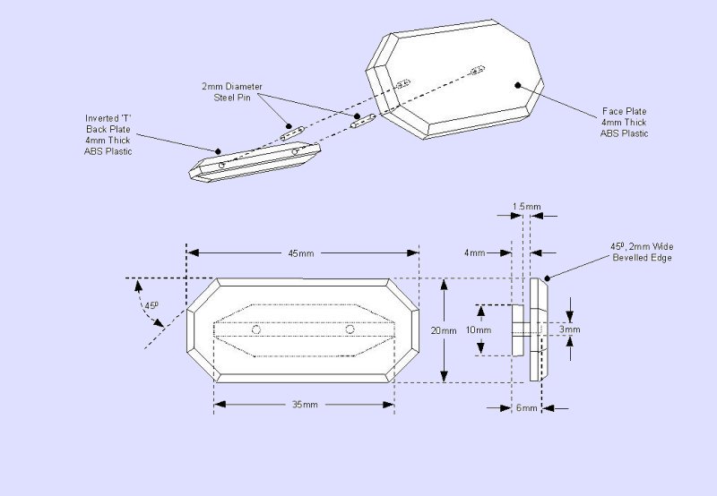
1. Holding the face plate and back plate together in the correct 'final' position (both long axes aligned centrally and the back plate centred onto the back of the face plate in an inverted 'T' position - bottom/foot of the 'T' against the back of the face plate) clamp them across the corner of the vice such that both the holes in the back plate are visible. Using a hammer and a small panel pin or similar mark through the holes into the back of the face plate.

2. Disassemble the face plate from the back plate. In the back of the face plate, at the marks made, drill 2 x 2mm holes to a depth of 2mm i.e. only half way through the face plate.

3. Glue a 2mm diameter, 6mm long steel pin into each hole in the back of the face plate ensuring the pin is fully located into the hole.

4. Using the methylated spirit (or similar) and applicator cloth or cotton bud, thoroughly clean the mating surfaces of the front plate and back plate and allow to dry.

5. Apply glue to the mating surfaces of the face plate and back plate and slide the back plate over the steel pins and into contact with the back of the face plate.

6. The cover is now completed and should be put aside for at least 24 hours to allow the glue to fully cure.

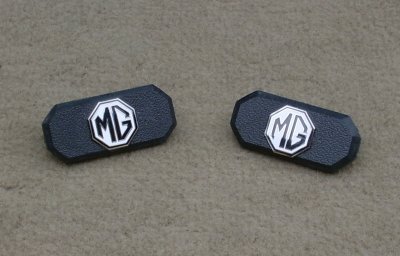
Although each cover is now complete the face of the cover can be further decorated. Those shown in the photograph have had a 16mm x 16mm lapel pin badge glued centrally on the face plate. This requires a very small clearance hole to be drilled through the centre point of the face plate to clear the 'pin' at the rear of the lapel badge. Additionally a larger diameter hole is then drilled concentric with the first small hole to a depth of 3mm to clear the locating stub on the back of the lapel badge and allow it to sit flat on the face plate. The lapel badge is then simply glued into position.


Installation

Each cover is installed by simply pushing the back plate through the slot in the rubber face of the cheater panel such that it 'slots home' (it may need a bit of coaxing with a small screwdriver), the inverted 'T' section locating the cover firmly in position.

The photographs below show the final installation of the cover panel on each door.

Now that looks much better!